Introduction
The smooth operation and safety of modern vehicles rely on a multitude of complex systems working seamlessly together. One such critical component that often goes unnoticed is the wheel speed sensor.
These small but mighty devices play an indispensable role in ensuring optimal vehicle performance, safety, and control. In this article, we will delve into the intricate workings of wheel speed sensors, exploring their significance and how they contribute to the overall functionality of modern vehicles.
Importance of Wheel Speed Sensors in Modern Vehicles
As technology continues to advance at an unprecedented pace, so do the expectations placed on our vehicles. Wheel speed sensors are among the crucial components that have been refined and integrated into today’s automobiles to enhance safety and performance.
The sensors provide real-time data regarding each wheel’s rotational speed, allowing various vehicle systems to make informed decisions concerning braking, traction control, stability management, tire pressure, and more. One crucial aspect where wheel speed sensors prove their significance is in preventing wheel lock-up during braking.
By continuously monitoring individual wheel speeds the sensors can provide vital information for anti-lock braking systems (ABS). ABS utilizes this data to modulate brake pressure on specific wheels as needed to prevent skidding or lock-up while maintaining steering control. This not only shortens stopping distances but also ensures that drivers can maintain command over their vehicles even in emergency situations.
Wheel speed sensors also play a pivotal role in optimizing traction control systems (TCS). These systems rely on accurate measurements of individual wheel speeds to assess slip conditions during acceleration or cornering maneuvers. By monitoring variations in rotational speeds between wheels, TCS can intervene by applying brakes or adjusting engine power distribution to prevent excessive wheelspin or loss of traction. This intervention helps drivers maintain stability and enhances vehicle handling in challenging road conditions such as rain-soaked or icy roads.
Wheel speed sensors act as vigilant guardians within a vehicle’s intricate network of safety mechanisms and performance-enhancing systems. By providing precise and real-time data on wheel rotational speeds these sensors enable advanced functionalities like anti-lock braking systems (ABS), traction control systems (TCS), stability management, and more. Their presence is undeniably vital in modern vehicles, elevating both safety and performance to new heights.

The Basic Functioning of Wheel Speed Sensors
Types of Wheel Speed Sensors: Active and Passive
There are two main types of wheel speed sensors: active and passive.
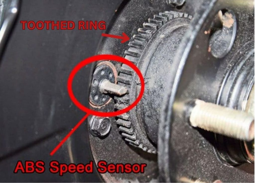
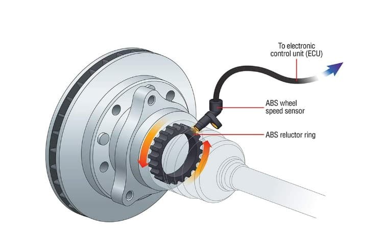
Active wheel speed sensors utilize electromagnetic induction principles to detect wheel rotations accurately. They consist of a toothed ring or reluctor ring mounted on each wheel hub assembly. As the teeth pass through a magnetic field generated by an electromagnetic sensor, an alternating current (AC) signal is induced within the sensor coil. This AC signal is then converted into a digital form by the ECU for further analysis.
Passive wheel speed sensors rely on external power sources such as an ABS module or ECU for operation. These sensors use either a coil or Hall-effect sensor element placed in close proximity to a rotating toothed ring or reluctor ring. As the teeth move past the sensor they cause changes in magnetic fields that induce voltage variations across the coil or Hall-effect element. The ECU measures these voltage changes to determine the rotational speed of each wheel.
Placement and Number of Sensors in a Typical Vehicle
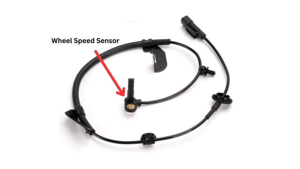
The placement and quantity of wheel speed sensors in a vehicle vary depending on the specific model and its intended functionality. In most cases each individual wheel is equipped with a dedicated sensor to provide accurate data for precise monitoring. This means a typical vehicle with four wheels will incorporate four wheel speed sensors, one for each wheel.
Regarding their physical location the sensors are strategically positioned near the brake components or within the wheel hub assembly. This placement ensures optimal accuracy in measuring rotational speed while also being shielded from external elements.
The exact installation points will differ across vehicle makes and models but they are generally located within close proximity to the teethed rings or reluctor rings attached to the wheels’ rotating components. By having multiple sensors distributed across all wheels, vehicles can accurately monitor individual wheel speeds and detect any discrepancies that may signal potential issues like locked-up brakes or loss of traction on specific wheels.
Active Wheel Speed Sensors
Principle Behind Active Wheel Speed Sensors
Wheel speed sensors play a crucial role in modern automotive systems and active sensors are one of the primary types used. The principle guiding their operation lies in the utilization of electromagnetic induction. This fascinating concept relies on Faraday’s law of electromagnetic induction which states that a changing magnetic field can induce an electric current in a conductor. In the case of active wheel speed sensors, this conductor is a toothed ring or reluctor ring, typically made of ferromagnetic material and rotates with the wheel.
Use of Electromagnetic Induction
As the toothed ring spins within close proximity to the sensor it passes through a magnetic field generated by a small permanent magnet or electromagnet housed within the sensor itself. This interaction between the rotating reluctor ring and magnetic field is where electromagnetic induction comes into play. As teeth on the reluctor ring move past the magnetic field they cause changes in the flux lines (magnetic lines of force) passing through them. This change in flux induces alternating current (AC) signals within a coil or set of windings located inside the sensor.
The frequency and amplitude of these AC signals are directly proportional to the rotational speed and direction of movement for each individual wheel. The faster the rotation, for instance during high-speed driving, or when decelerating rapidly due to braking – both scenarios result in higher frequencies and amplitudes detected by active wheel speed sensors.
Conversion of AC Signal to Digital Signal
To make this information useful for vehicle systems and driver assistance features such as ABS (Anti-lock Braking System), TCS (Traction Control System), or ESC (Electronic Stability Control), it is crucial to convert these AC signals into digital signals easily interpreted by the vehicle’s electronic control unit (ECU). This conversion process is achieved through an analog-to-digital converter (ADC) integrated within the sensor or through a separate module in the vehicle’s electronic system. The ADC measures the frequency and amplitude of the AC signals generated by the active wheel speed sensor, quantifying them into discrete digital values that can be easily processed and interpreted by the ECU.
Through this conversion real-time data on each wheel’s rotational speed becomes available for analysis and utilization in various safety and performance systems. Active wheel speed sensors showcase an elegant application of electromagnetic induction principles.
Passive Wheel Speed Sensors
Principle Behind Passive Wheel Speed Sensors
Passive wheel speed sensors, also known as passive magnetic sensors, operate on a different principle compared to their active counterparts. Instead of generating a signal themselves, passive sensors rely on an external power source to induce a voltage across the sensor coil or Hall-effect sensor element. This external power source is typically provided by the vehicle’s anti-lock braking system (ABS) module or electronic control unit (ECU).
Reliance on External Power Source
The reliance on an external power source is a key characteristic of passive wheel speed sensors. When the toothed ring or reluctor ring attached to the wheel rotates, it creates changes in the magnetic field around the sensor coil or Hall-effect sensor element. This variation in magnetic field induces a corresponding change in voltage across the sensor. The frequency and amplitude of these voltage changes directly correlate with the rotational speed of the wheel. Unlike active wheel speed sensors that generate their own alternating current (AC) signal, passive sensors do not have an internal power supply.
They depend on the ABS module or ECU to provide continuous power for their operation. By utilizing this external power source passive sensors are able to accurately measure rotational speeds without requiring additional components for signal generation.
The variation in voltage caused by changes in the magnetic field is crucial for accurate wheel speed measurement. As each toothed ring passes by the sensor coil or Hall-effect sensor element, it alters the intensity and orientation of the magnetic field surrounding it. This alteration generates fluctuations in voltage induction across the sensor elements—higher frequency and amplitude for faster rotation and lower frequency and amplitude for slower rotation. The progressive change in these induced voltages allows vehicle systems like ABS, TCS, indirect TPMS, and ESC to determine not only individual wheel speeds but also any irregularities among them.
By analyzing these variations within the sensor signals the ECU can identify wheel lock-ups, wheel slip or skid, low tire pressure, and even potential loss of traction. This information plays a vital role in ensuring optimal brake force distribution, stability control, and overall vehicle safety in various driving conditions.
Signal Processing and Analysis by the ECU
The Role of the Electronic Control Unit
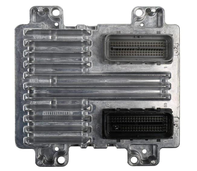
The electronic control unit (ECU) plays a crucial role in deciphering the signals received from the wheel speed sensors. It acts as the brain of the vehicle’s control system, processing and analyzing the data to ensure optimal performance and safety. The ECU is equipped with highly sophisticated algorithms that enable it to interpret the frequency or voltage changes detected by the sensors.
Calculation of Wheel Speeds
Once the ECU receives data from each wheel speed sensor it uses advanced algorithms to calculate individual wheel speeds. This calculation is primarily based on changes in frequency or voltage detected by these sensors. By tracking variations in these parameters over time the ECU can precisely determine how fast each wheel is rotating.
Comparison of Wheel Speeds
Another vital function performed by the ECU is comparing the speeds of different wheels to identify inconsistencies or anomalies. By continuously monitoring and analyzing data from all four wheels it can detect any discrepancies that may indicate potential issues with tire pressure, brake calipers, or wheel bearing malfunction. This comparison allows for early detection of problems.
Applications of this Information for Various Vehicle Systems
The information gathered and processed by the ECU regarding individual wheel speeds has wide-ranging applications across different vehicle systems:
1. Anti-lock braking system (ABS) functionality: The ABS relies on precise monitoring of individual wheel speeds to prevent wheels from locking up during sudden braking. By modulating brake pressure to each wheel independently based on their relative rotational velocities, which is determined by wheel speed sensors, it ensures optimal stopping distances and steering control.
2. Traction control system (TCS) operation: TCS uses wheel speed sensors to monitor any wheel slip during acceleration. If it detects a significant difference in wheel speeds indicating loss of traction, the TCS intervenes by reducing engine power or applying braking force to the specific wheel(s) to restore grip and prevent wheelspin.
3. Electronic stability control (ESC): ESC systems utilize data from wheel speed sensors, along with other sensors like yaw rate and steering angle sensors, to assess vehicle stability during cornering or sudden maneuvers. By selectively applying brakes to individual wheels the ESC can counteract oversteer or understeer tendencies and help maintain vehicle stability.
4. Tire pressure monitoring systems (TPMS): Indirect TPMS uses wheel speed sensor data to monitor the tire pressure. It works on the principle that a deflated tire will have a smaller rolling radius, resulting in a higher rotational speed. If the ECU detects one wheel rotating at a significantly different rate than the others, it may infer a potential loss of tire pressure and alert the driver.
5. Adaptive Cruise Control (ACC) and Autonomous driving systems: These advanced systems rely heavily on wheel speed sensor data along with a myriad of other sensor data to control the vehicle’s speed and maintain safe distances from other road users. In situations of lower tire pressure the vehicle dynamics can change and understanding this helps these systems adapt and maintain safety and performance standards.
Conclusion
Wheel speed sensors play a pivotal role in modern vehicles by providing crucial data on individual wheel speeds. The electronic control unit (ECU) acts as the central processing hub that interprets these signals and applies them across various systems for enhanced safety and performance.
The ECU’s ability to calculate individual wheel speeds, compare them for anomalies, and utilize this information for systems like ABS, TCS, TPMS, and ESC ensures optimal control in diverse driving conditions. With these advancements in technology, vehicles are now equipped with sophisticated mechanisms that can better protect drivers and passengers while delivering an enjoyable driving experience.